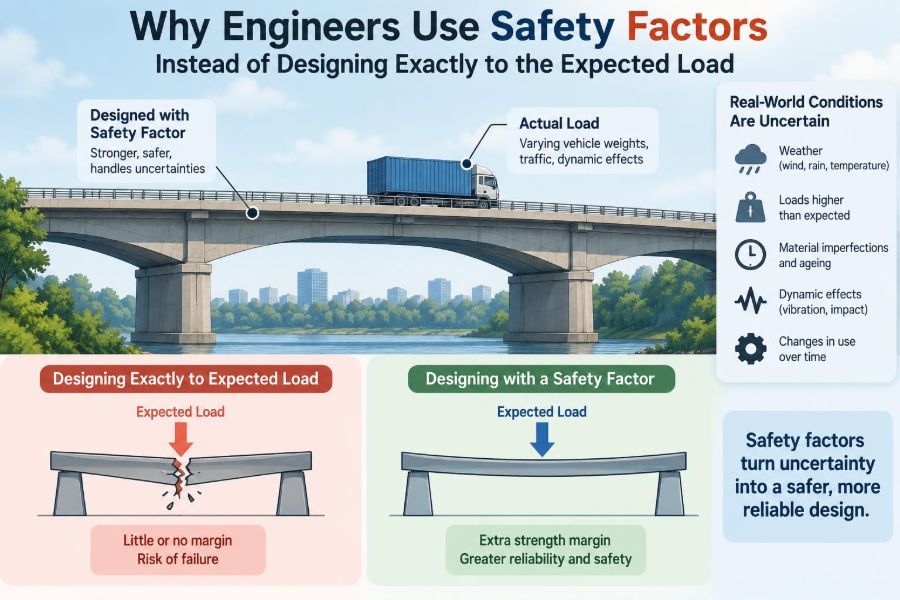

A shelf is expected to hold a few boxes. A bridge is expected to carry traffic. A lifting hook is expected to raise a known mass. It can seem reasonable to calculate that expected load, choose a component just strong enough to carry it, and stop there.
That approach would work only in an unusually tidy world: loads would never vary, materials would always match their datasheet values, manufacturing would be flawless, and nothing would age, corrode, vibrate, or be used incorrectly.
Real engineering takes place outside that tidy world. A delivery truck may be heavier than anticipated, a gust may arrive with a rare intensity, or a small crack may grow over years of repeated loading.
That is why engineers do not normally design exactly to the expected load. They use safety factors—deliberate margins that turn an uncertain prediction into a design with a defensible level of reliability.
🧱 The Basic Idea Behind a Safety Factor
A safety factor compares a component’s available strength or capacity with the demand placed on it. In its simplest form, it can be written as:
Safety factor = failure capacity / applied loadIf a part can theoretically fail at 10 kN and the relevant load is 5 kN, the simple ratio is 2. The component has twice the calculated failure capacity required by that load case.
This does not mean the engineer expects the part to use only half its capability. It means the design includes margin for the gap between a calculation and reality.
🎯 Expected Load Is an Estimate, Not a Promise
An expected load is usually a model of normal service, not an absolute upper boundary. People may use a floor differently than planned, stored goods may be rearranged, or equipment may be upgraded during a building’s life.
Even a load that appears fixed can vary. The actual mass of a machine includes tolerances, attachments, contents, and occasionally human actions such as impact during installation.
Engineering begins by asking not just, “What load is likely?” but also, “What credible conditions could make this load larger or more damaging?”
🌦️ Nature Does Not Deliver Average Conditions
Environmental actions are particularly variable. Wind changes direction and speed, rainfall accumulates differently across a roof, temperatures expand and contract materials, and earthquakes produce dynamic motion rather than a calm static push.
Designing a roof only for an average snow condition, for example, would ignore drifting, local accumulation, and unusual weather events that the structure may reasonably need to endure.
Relevant design rules translate regional hazards and structural behavior into specified load cases. Safety margins are part of that wider framework, not a substitute for considering the hazard itself.
📐 Strength Values Are Also Uncertain
Material strength is not one perfectly fixed number. Two pieces of steel, concrete, timber, or composite material can differ because of composition, curing, grain direction, moisture, defects, and manufacturing variation.
Laboratory test data describes a population of specimens. A design must account for the lower end of plausible material performance, rather than assuming every piece will achieve a favorable test result.
This distinction matters most for materials whose properties are naturally variable or strongly dependent on installation conditions, such as concrete and timber.
🏭 Manufacturing Creates Real-World Variation
Dimensions have tolerances. Welds can contain imperfections. Holes may be slightly oversized, surfaces may be rougher than assumed, and assembly may introduce residual stress or misalignment.
Good quality control reduces these uncertainties, but it does not erase all variation. Design margins work alongside inspection, testing, qualified procedures, and traceable materials.
A safety factor should never be treated as permission for careless manufacture. It is protection against the remaining variation in a controlled process, not compensation for ignoring basic workmanship.
🔍 Models Simplify the Physical System
Engineering calculations deliberately simplify reality. A beam may be treated as straight, supports may be assumed rigid, and loads may be represented at idealized locations. These assumptions make analysis possible, but each has limits.
For an ordinary component under a familiar load, the simplification may be excellent. For a complicated joint, a slender shell, or a structure with interacting parts, the difference between model and behavior can matter greatly.
Safety factors provide some resilience against modest modeling uncertainty. Where uncertainty is large, engineers need better analysis, testing, monitoring, or redesign—not merely a much bigger multiplier.
🧠 Load Capacity Is Not the Same as Failure Load
“Failure” can mean several different things. A cable might break, but a floor can become unusable long before it collapses because it deflects too much or vibrates uncomfortably.
A pressure vessel may need to avoid leakage, a machine shaft may need to avoid permanent twist, and a precision instrument may need to remain accurately aligned. Each condition has a different acceptable limit.
Engineers therefore check both ultimate limit states, associated with collapse or rupture, and serviceability limit states, associated with normal function, appearance, comfort, or durability.
⚖️ Yielding and Breaking Need Different Attention
Many ductile metals yield before they fracture. Yielding means the material begins to deform permanently; after unloading, it does not fully return to its original shape.
For a bracket, limited yielding might be unacceptable because it misaligns equipment. For another system, controlled yielding can provide warning and redistribute force before a more serious failure occurs.
Brittle materials can fail with much less visible deformation. Their design often demands careful control of stress concentrations, defects, and uncertainty because there may be little warning before fracture.
🔄 Repeated Loads Can Be More Damaging Than One Big Load
A part can survive a single moderate load yet fail after many repetitions. This process is called fatigue. It is common in rotating shafts, vehicle suspensions, bridges, aircraft structures, and vibrating machinery.
Small cyclic stresses can initiate a crack at a notch, weld toe, or surface imperfection. The crack may grow gradually until the remaining section can no longer carry the load.
A static safety factor alone does not answer a fatigue problem. Engineers use fatigue data, stress-range calculations, detail classifications, inspection plans, and crack-growth assessments where appropriate.
⏳ Time Changes Materials and Structures
Some materials lose effective capacity with time or exposure. Corrosion reduces metal thickness, ultraviolet exposure can affect polymers, moisture can alter timber, and high temperatures can cause creep—slow deformation under sustained stress.
Wear can enlarge clearances and remove protective coatings. Freeze-thaw cycles, chemical attack, and settlement can change how a structural system distributes loads.
Durability design is therefore connected to safety factors but is not identical to them. Protective detailing, drainage, coatings, maintenance access, and inspection intervals often matter just as much.
💥 Dynamic Loads Are Not Just Heavier Static Loads
When a load starts, stops, drops, collides, or vibrates, acceleration creates forces beyond the object’s weight. A crane hoist that snatches a load, for instance, can create much larger force than gently supporting the same mass.
Resonance adds another complication. If repeated forcing occurs near a system’s natural frequency, motion and stress can build dramatically.
Engineers address dynamics using suitable load combinations, impact allowances, damping assumptions, dynamic analysis, and sometimes physical tests. A generic safety factor cannot reliably represent every dynamic mechanism.
🧩 Connections Often Control the Design
Members receive attention because they are visible, but connections frequently determine whether a system performs as intended. Bolts, welds, adhesive joints, anchors, and bearing surfaces transfer load from one part to another.
A strong beam attached with an inadequate connection is not a strong assembly. Eccentricity—where the force acts away from the intended centerline—can introduce bending and prying forces that a simple axial calculation misses.
Design checks must follow the entire load path, from where force enters the structure to where it reaches the ground or another supporting system.
🏗️ Load Paths Must Remain Intact
A load path is the continuous route by which force travels through a structure. On a building roof, snow load may pass through sheathing, rafters, walls, connections, foundations, and finally into soil.
Every stage needs adequate capacity and compatible stiffness. If one link is weak, the assumed path may change, concentrating force elsewhere.
Safety factors on isolated parts cannot correct a missing or misunderstood load path. Clear structural arrangement is often safer and easier to inspect than a complicated arrangement with large nominal margins.
🛡️ Redundancy Adds a Different Kind of Safety
Safety factor is capacity margin in a component or system. Redundancy is the presence of alternative paths that allow a system to continue carrying load after a local problem.
A multi-member framework can sometimes redistribute forces when one member is damaged, while a single critical hanger may have no alternate path. The consequences are very different even if both parts have the same calculated safety factor.
Redundancy can improve robustness, but it must be analyzed. Load redistribution may overload neighboring members if it is assumed without checking their response.
📊 Two Common Design Philosophies
Engineers use different safety formats depending on the discipline, material, and governing code. Two broad approaches are common.
| Approach | Core idea | Typical use in reasoning |
|---|---|---|
| Allowable-stress or working-stress design | Keep service stresses below an allowed value derived from material strength. | Uses an overall margin between expected working conditions and failure-related strength. |
| Limit-state design | Apply factors to loads and reduce nominal resistance, then check specific failure and service conditions. | Separates uncertainty in loading from uncertainty in resistance more explicitly. |
Neither label tells the whole story. Actual code provisions include definitions, combinations, material rules, detailing requirements, and validity limits that must be used together.
➗ Why Partial Factors Are More Informative
A single global safety factor treats all uncertainty as if it comes from one source. In reality, uncertainty in permanent weight differs from uncertainty in occupancy, wind, manufacturing, and material strength.
Limit-state methods often use partial factors: load effects may be increased and resistance may be reduced. This creates a more targeted margin for different situations.
For example, a variable imposed load may receive different treatment from a well-defined self-weight because their ranges and chances of occurring together are not the same.
🧮 Load Combinations Reflect Real Coincidences
A structure is rarely checked under one action at a time. It may carry self-weight, occupants, equipment, wind, temperature effects, and snow in combinations specified by the relevant design basis.
Not every maximum action is assumed to occur simultaneously. Doing so can be unrealistic, while ignoring combinations can be unsafe.
The purpose is not to guess the most dramatic-looking scenario. It is to evaluate credible combinations with rules developed for the type of structure and its intended environment.
🚧 Consequences Influence the Required Margin
A temporary hand tool, an industrial lifting device, and a public bridge do not present the same consequences if they fail. Exposure of people, difficulty of inspection, speed of failure, and potential for cascading damage all influence design decisions.
Higher consequences may justify more conservative assumptions, greater robustness, stricter fabrication control, more frequent inspection, or independent review.
This is not simply about making everything oversized. It is about matching the depth of protection to the risk created by failure.
🏠 A Simple Shelf Example
Imagine a wall-mounted shelf intended for books. A naïve calculation might total the expected books and select brackets that just support that mass.
A practical design also considers someone leaning on the shelf, uneven loading, the leverage created by a deep shelf, screw withdrawal from the wall, the actual wall material, and deterioration around fixings.
The useful lesson is that “the bracket is strong enough” is incomplete. The wall anchors, fasteners, installation quality, and load position may control the outcome.
🏗️ A Crane Hook Example
Consider a hypothetical lifting hook rated for a specified working load. The hook must account for more than the suspended mass: acceleration during lifting, off-center loading, repeated cycles, wear, surface damage, and the severe consequence of a dropped load.
Its design and use may therefore involve controlled geometry, material requirements, inspection for cracks or opening, marked load limits, and rules against side loading.
The safety margin is one layer in a system of controls. Training and inspection are not optional extras when lifting operations are involved.
📏 Bigger Is Not Always Safer
Increasing thickness or cross-section can reduce stress, but oversizing without thought can introduce new issues. Extra self-weight raises foundation loads, a stiffer member can attract more force in a shared system, and a bulky part may be difficult to fabricate or inspect.
Very high stiffness can also alter vibration behavior. Larger welds or abrupt changes in section can create fatigue-sensitive details if poorly designed.
Good engineering seeks an appropriate margin with sound geometry, material choice, detailing, and verification—not the largest possible component.
💰 Safety Factors Balance Risk and Resources
More margin generally requires more material, manufacturing effort, or operating restriction. Those costs are real, especially across large infrastructure or high-volume products.
But minimizing initial material cost can be false economy if it increases inspection burdens, outage risk, repair difficulty, or the consequences of an unexpected condition.
The aim is not to make risk vanish; that is usually impossible. It is to reduce risk to a level appropriate for the application using proportionate, evidence-based measures.
🧪 Testing Can Reduce Uncertainty—Within Limits
Prototypes, material coupons, proof tests, and full-scale tests can reveal behavior that calculations do not capture fully. Testing is especially valuable for new configurations, complicated connections, and products that will be manufactured repeatedly.
Yet a successful test is not universal proof. The tested item may not represent every production unit, every environment, or every long-term loading condition.
Test results must be interpreted with an understanding of test setup, measurement error, sample variation, and the failure modes that were or were not exercised.
🖥️ Software Does Not Remove Engineering Judgment
Analysis software can calculate thousands of forces rapidly, but it faithfully processes the inputs and assumptions it receives. A refined-looking color plot can still be wrong if restraints, loads, contact conditions, or material models are wrong.
Useful checks include hand estimates, equilibrium checks, mesh-sensitivity studies where relevant, comparison with known behavior, and review of deformed shapes.
Safety factors do not rescue an implausible model. Judgment is required before, during, and after computation.
🧰 Inspection Keeps the Design Assumptions Valid
Some designs depend on periodic inspection because damage can develop in service. A bridge bearing, lifting accessory, pressure system, or corroding connection may require planned examination to detect changes before capacity is compromised.
An inspection plan should identify what to look for, how often to look, who is qualified to assess it, and what action follows a finding.
Design life is therefore partly an operations question. The assumed safety margin can erode if maintenance that the design relies on never occurs.
⚠️ Common Misunderstandings About Safety Factors
- “A factor of two means twice as safe.” Safety is not a simple linear score; failure modes and uncertainties differ.
- “One large factor covers everything.” Fatigue, corrosion, buckling, vibration, and brittle fracture need specific checks.
- “The strongest material gives the safest design.” Geometry, connections, toughness, durability, and manufacturing can govern instead.
- “Code minimum is automatically optimal.” A code-based design may still need project-specific assessment for unusual conditions.
- “A safety factor excuses overload.” Rated limits and operating procedures remain essential.
📚 Codes Turn Experience Into Consistent Practice
Engineering standards and codes provide common methods for loads, material properties, combinations, detailing, and acceptance criteria. They embody accumulated technical knowledge and create a shared basis for design and review.
They are not interchangeable, and requirements vary by location, industry, material, and application. A structural building code is not a design manual for a medical device or a lifting accessory.
For regulated or safety-critical work, applicable current requirements and competent professional review matter. Simplified examples are useful for learning, not for authorizing real construction or operation.
🧭 A Practical Design Thought Process
Before choosing a margin, engineers typically build a structured picture of the problem:
- Define the intended function, service life, environment, and consequences of failure.
- Identify loads, their variability, and credible load combinations.
- Trace load paths and identify relevant failure and serviceability modes.
- Select applicable material data, design rules, and analysis methods.
- Apply appropriate factors and check detailing, fabrication, and installation.
- Specify inspection, maintenance, or operational limits where the design depends on them.
This process explains why selecting a safety factor is rarely the first or only design decision.
🧑🔧 Questions Working Engineers Should Keep Asking
Healthy skepticism improves designs. What assumption has the greatest influence on the answer? Which failure mode would occur first? Could a user load this in a way the model excludes? What changes after ten years outdoors?
Another valuable question is, “If this component deforms or fails, what happens next?” That question brings connections, redundancy, warning signs, and human exposure into the design conversation.
Clear documentation matters too. Future engineers and maintenance teams need to know the intended load limits, assumptions, materials, and inspection requirements.
✅ The Core Principle: Design for Uncertainty, Not Just Averages
Safety factors exist because engineering decisions must remain dependable despite variation in loads, materials, manufacture, analysis, environments, and use. They are a disciplined acknowledgment that an expected value is not a guaranteed value.
They work best when combined with appropriate load cases, failure-mode checks, durable detailing, quality control, inspection, and competent judgment. Used alone as a blunt multiplier, they can create false confidence.
The strongest design is not necessarily the heaviest one. It is the one whose margins and assumptions match the ways it can realistically be loaded, made, used, and maintained.
Engineers use safety factors not because calculations are useless, but because responsible calculations include the uncertainty that reality always brings. 📐🛡️🏗️