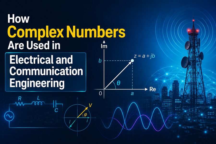

Complex numbers can seem abstract when they are first introduced in mathematics. They contain a real part and an imaginary part, often written in the form:
z = a + jb
where a is the real component, b is the imaginary component, and electrical engineers usually use j instead of i because the letter i is commonly reserved for electric current.
Despite their abstract appearance, complex numbers are among the most practical mathematical tools in electrical and communication engineering. They make it much easier to analyze alternating-current circuits, electromagnetic waves, filters, oscillators, modulation systems, antennas, control systems, and digital communications.
The reason is simple: many electrical quantities change continuously in both magnitude and phase. Complex numbers provide a compact way to represent both at the same time. ⚡📐
Instead of solving complicated trigonometric equations repeatedly, engineers can often replace oscillating sine and cosine functions with elegant algebra involving complex numbers.
🧠 What Is a Complex Number?
A complex number contains two components:
z = a + jb
For example:
z = 3 + j4
The number 3 is the real part, while 4 is the imaginary part.
Complex numbers can also be represented graphically on the complex plane.
The horizontal axis represents the real component, while the vertical axis represents the imaginary component.
This means the complex number:
3 + j4
can be represented as a point located 3 units horizontally and 4 units vertically.
Using the Pythagorean theorem, its magnitude is:
|z| = √(3² + 4²) = 5
Its angle represents its direction in the complex plane.
This ability to describe both magnitude and angle is exactly what makes complex numbers so useful in engineering. 📊
🔄 Why Oscillating Signals Are Naturally Connected to Complex Numbers
Many electrical signals are sinusoidal.
For example, an alternating voltage might be written as:
v(t) = Vₘ cos(ωt + φ)
where:
- Vₘ is the amplitude
- ω is angular frequency
- t is time
- φ is phase angle
Working directly with sine and cosine equations can become cumbersome, especially when several signals interact.
Complex numbers provide a more convenient representation through Euler’s formula:
e^(jθ) = cos θ + j sin θ
This equation creates a powerful connection between exponential functions and sinusoidal waves.
A sinusoidal signal can therefore be associated with a rotating complex quantity.
Instead of repeatedly manipulating trigonometric expressions, engineers can perform ordinary algebra using complex numbers and then extract the real physical signal afterward.
⚡ Phasors in AC Circuit Analysis
One of the most common applications of complex numbers is phasor analysis.
A phasor is a complex-number representation of a sinusoidal quantity at a particular frequency.
Suppose an AC voltage is:
v(t) = 100 cos(ωt + 30°)
Its phasor can be represented approximately as:
V = 100∠30°
This notation tells the engineer two things immediately:
- Magnitude = 100
- Phase angle = 30°
Instead of keeping track of the time-dependent cosine function throughout a circuit calculation, engineers work with the phasor.
This makes AC circuit analysis dramatically easier. 🔌
🌀 Why Phase Matters
Two sinusoidal signals can have the same frequency and amplitude but reach their peaks at different times.
This difference is called a phase difference.
For example, one signal might be:
cos(ωt)
while another is:
cos(ωt + 90°)
The second signal leads the first by 90 degrees.
Phase relationships are extremely important in AC power systems, filters, amplifiers, communication receivers, and radio-frequency circuits.
Complex numbers encode phase naturally as an angle.
That is one reason they are far more convenient than working only with real numbers.
🔌 Resistance, Inductance, and Capacitance
In basic DC circuits, Ohm’s law is:
V = IR
where resistance R is a real number.
In AC circuits, inductors and capacitors complicate things because voltage and current may no longer be in phase.
Engineers solve this problem using impedance.
Impedance is the AC equivalent of resistance and is usually represented by the complex quantity:
Z = R + jX
where:
- R is resistance
- X is reactance
Reactance represents how inductors and capacitors oppose changing current or voltage.
🧲 Inductive Impedance
For an ideal inductor:
ZL = jωL
where:
- j represents the imaginary unit
- ω is angular frequency
- L is inductance
The factor j indicates a 90-degree phase relationship between voltage and current.
As frequency increases, inductive impedance increases.
This explains why inductors oppose high-frequency signals more strongly than low-frequency signals.
🔋 Capacitive Impedance
For an ideal capacitor:
ZC = 1/(jωC)
which can also be written as:
ZC = -j/(ωC)
where C is capacitance.
The negative imaginary component indicates that the capacitor creates a phase relationship opposite to that of an inductor.
As frequency increases, capacitive impedance decreases.
Complex-number notation allows engineers to combine resistors, capacitors, and inductors using algebraic techniques similar to ordinary resistor calculations.
⚙️ Complex Ohm’s Law
In AC circuit analysis, Ohm’s law becomes:
V = IZ
Here, voltage, current, and impedance can all be complex quantities.
Suppose:
Z = 4 + j3 Ω
The magnitude of the impedance is:
|Z| = √(4² + 3²) = 5 Ω
Its phase angle indicates how much voltage and current are shifted relative to each other.
Instead of separately solving magnitude and phase equations, engineers can calculate everything using a single complex expression. 🧮
📐 Polar Form Makes Engineering Easier
Complex numbers can be written in rectangular form:
a + jb
or polar form:
r∠θ
where:
- r is magnitude
- θ is phase angle
For multiplication and division, polar form is especially convenient.
If two quantities are multiplied, their magnitudes multiply and their angles add.
For example:
2∠30° × 3∠20° = 6∠50°
Similarly, division subtracts the angles.
This makes calculations involving amplifiers, filters, and communication signals much simpler.
📊 Complex Power in AC Systems
Complex numbers are also used to describe electrical power.
In AC engineering, complex power is written as:
S = P + jQ
where:
- P = real or active power
- Q = reactive power
- S = complex power
Active power performs useful work, such as running motors or producing heat.
Reactive power represents energy repeatedly stored and returned by inductors and capacitors.
The magnitude of complex power is called apparent power.
Complex-number analysis helps power engineers understand power factor, transmission losses, generators, transformers, and industrial electrical systems. ⚡🏭
📡 Complex Numbers in Communication Engineering
Complex numbers become even more important in communication systems.
Radio, Wi-Fi, mobile networks, satellite communication, radar, and digital communication all involve rapidly oscillating electromagnetic signals.
A radio-frequency signal can often be represented more conveniently using a complex envelope rather than directly tracking every oscillation of its carrier wave.
This greatly simplifies mathematical analysis and digital signal processing.
📶 In-Phase and Quadrature Components
Communication engineers often represent a signal using two components:
- I — In-phase component
- Q — Quadrature component
These components are separated by 90 degrees.
Together they form a complex signal:
s = I + jQ
This is called an I/Q representation.
Instead of describing an RF signal only by its instantaneous voltage, the complex representation captures both amplitude and phase.
I/Q signals form the foundation of many modern communication technologies. 📡
🛰️ Quadrature Amplitude Modulation
One important application is Quadrature Amplitude Modulation, or QAM.
QAM transmits information by changing both the amplitude and phase of a carrier signal.
Each transmitted symbol can be represented as a point on the complex plane.
For example, 16-QAM uses 16 possible symbol positions.
Each point corresponds to a particular combination of I and Q values.
Higher-order systems such as:
- 64-QAM
- 256-QAM
- 1024-QAM
can encode more bits in each transmitted symbol.
These modulation techniques are widely used in technologies such as Wi-Fi, cable communications, cellular networks, and digital broadcasting. 📶
🌌 Constellation Diagrams
A constellation diagram is a graphical representation of digital modulation symbols on the complex plane.
The horizontal axis represents the I component.
The vertical axis represents the Q component.
Each point represents a valid transmitted symbol.
In an ideal system, received points would land exactly where expected.
In real systems, noise, distortion, interference, and phase errors cause received points to move away from their ideal locations.
Engineers study constellation diagrams to evaluate communication quality.
This is another example of complex numbers becoming directly visible as an engineering tool. 🎯
📻 Fourier Analysis and Complex Exponentials
Communication engineering relies heavily on the Fourier transform.
The Fourier transform decomposes a signal into frequency components.
Instead of thinking of a complicated waveform only in the time domain, engineers can study how much energy it contains at different frequencies.
Complex exponentials are fundamental to Fourier analysis.
A frequency component is often represented using:
e^(jωt)
The result of a Fourier transform is generally complex.
Its magnitude tells engineers how strong a frequency component is, while its phase provides information about timing and waveform structure.
Fourier analysis is essential for:
- Audio processing
- Wireless communications
- Image processing
- Radar
- Filter design
- Spectrum analysis
- Data transmission
🎚️ Filters and Frequency Response
Electronic filters are designed to allow some frequencies through while reducing others.
For example, a low-pass filter passes low-frequency signals and suppresses high-frequency signals.
Engineers describe a filter using a transfer function.
At a particular frequency, the transfer function is often complex:
H(jω)
Its magnitude tells us how much the filter amplifies or attenuates the signal.
Its phase tells us how much the filter shifts the signal in time or phase.
A complete understanding of filter behavior therefore requires both parts.
Complex numbers provide them simultaneously. 🎛️
📈 Bode Plots
Engineers frequently display system frequency response using Bode plots.
One graph shows magnitude versus frequency.
Another shows phase versus frequency.
Although Bode plots appear as ordinary graphs, the underlying calculations often come from evaluating complex transfer functions.
They are widely used in:
- Amplifier design
- Control engineering
- Filters
- Power supplies
- Communication circuits
📡 Antennas and Electromagnetic Waves
Electromagnetic fields also involve magnitude and phase.
When engineers analyze antennas, they often use complex quantities to represent electric and magnetic fields.
Complex numbers help describe:
- Wave propagation
- Reflection
- Transmission
- Antenna impedance
- Polarization
- Phase differences
- Standing waves
An antenna’s impedance, for example, might be expressed as:
Z = 50 + j10 Ω
The real part represents resistive behavior, while the imaginary part represents reactive behavior.
Engineers often try to reduce unwanted reactance and match antenna impedance to transmission lines for efficient power transfer.
🌐 Transmission Lines
At high frequencies, ordinary wires behave differently from simple low-frequency circuit connections.
Signals propagate along them as electromagnetic waves.
Transmission lines such as coaxial cables and printed-circuit-board traces are described using quantities such as:
- Characteristic impedance
- Reflection coefficient
- Propagation constant
These quantities are frequently complex.
Complex numbers allow engineers to calculate how signals are reflected, delayed, attenuated, and phase shifted as they move through a transmission line.
🔄 The Reflection Coefficient
When a transmission line is connected to a mismatched load, part of the signal can reflect backward.
The reflection coefficient is commonly represented as:
Γ
and is generally a complex number.
Its magnitude tells engineers how large the reflected wave is.
Its angle indicates the reflected wave’s phase.
This information is central to RF engineering and antenna matching.
Tools such as the Smith chart provide a graphical way to work with complex impedances and reflection coefficients.
🧭 The Smith Chart
The Smith chart is one of the most recognizable tools in radio-frequency engineering.
Although it may initially look complicated, it is essentially a specialized plot for visualizing complex impedance and admittance.
RF engineers use Smith charts to:
- Design impedance-matching networks
- Analyze transmission lines
- Evaluate antennas
- Calculate reflection
- Tune microwave circuits
The chart transforms complex-number calculations into convenient geometric operations. 📡⭕
📲 Complex Numbers in Digital Signal Processing
Digital signal processors frequently perform operations on complex numbers.
For example, algorithms such as the Fast Fourier Transform, or FFT, commonly produce complex-valued outputs.
Digital receivers may process I/Q samples as complex numbers.
This allows software to efficiently perform:
- Frequency translation
- Filtering
- Demodulation
- Synchronization
- Channel estimation
- Spectrum analysis
Modern software-defined radios depend heavily on this approach.
Instead of building every radio function using analog components, a digital system can process complex-valued signals mathematically.
📶 OFDM and Modern Wireless Networks
Many modern wireless systems use Orthogonal Frequency-Division Multiplexing, or OFDM.
OFDM divides a communication channel into many closely spaced subcarriers.
Each subcarrier can carry digitally modulated data.
The transmitter commonly uses an inverse FFT to generate the waveform, while the receiver uses an FFT to recover the individual subcarriers.
Because FFT operations naturally involve complex numbers, complex arithmetic is deeply embedded in technologies based on OFDM.
This technique is important in systems such as Wi-Fi and modern cellular communications. 📱📡
🎯 Channel Estimation
Wireless signals are affected by buildings, terrain, movement, and reflections.
Multiple copies of a signal can arrive at the receiver with different delays and phases.
Engineers model these effects using complex-valued channel coefficients.
A coefficient may describe both:
- How much the signal’s amplitude changes
- How much its phase changes
Receivers estimate these complex coefficients and compensate for them.
Without complex-number mathematics, modern high-speed wireless communication would be much harder to implement.
📡 Beamforming and Phased Arrays
Modern radar and wireless systems increasingly use phased-array antennas.
Instead of using one antenna, the system uses many antenna elements.
By carefully adjusting the relative phase of the signal at each element, the combined radio waves can reinforce one another in a desired direction.
The required amplitudes and phase shifts are naturally represented by complex numbers.
This technique is called beamforming.
Beamforming is used in:
- Radar
- Satellite communication
- 5G and other cellular systems
- Wi-Fi
- Radio astronomy
- Military sensing systems
Complex arithmetic makes it possible to coordinate many antenna elements precisely. 📡🎯
🔊 Complex Numbers in Audio and Acoustics
Audio engineers also use complex numbers when analyzing sound signals and electronic audio systems.
Frequency-response measurements are often complex because audio equipment changes both amplitude and phase.
Complex mathematical techniques can help model:
- Loudspeakers
- Microphones
- Equalizers
- Digital audio filters
- Room acoustics
Although listeners hear real-valued sound pressure, complex mathematics provides an efficient internal representation for analyzing it.
⚙️ Control Engineering
Complex numbers also play a major role in control systems.
Engineers analyze poles and zeros of transfer functions in the complex plane.
The locations of these poles can determine whether a system is stable, oscillatory, or unstable.
For example, control engineers may use complex-number methods when designing:
- Aircraft autopilots
- Motor controllers
- Industrial robots
- Power converters
- Vehicle control systems
The imaginary component often relates to oscillatory behavior, while the real component indicates whether oscillations grow or decay over time.
🧮 Why Engineers Do Not Simply Use Sines and Cosines
In principle, many engineering problems could be solved without complex numbers.
Engineers could separately track sine waves, cosine waves, amplitudes, and phase shifts.
But the equations would become much longer and more difficult.
Complex numbers combine these related quantities into a single mathematical object.
For example, instead of independently calculating two phase-shifted components, an engineer can perform one multiplication involving complex numbers.
This makes the mathematics:
- Shorter
- Easier to organize
- Easier to program
- Less error-prone
- More powerful for large systems
The imaginary part is therefore not “imaginary” in the sense of being useless.
It is a mathematical coordinate that helps encode physically meaningful information.
💻 Computers Perform Complex Arithmetic Too
Modern engineering software can perform millions or billions of complex-number calculations.
Programs used for:
- Circuit simulation
- RF design
- Signal processing
- Electromagnetic modeling
- Radar processing
- Wireless communications
routinely store numbers as pairs containing real and imaginary components.
Digital signal-processing chips may even include hardware instructions optimized specifically for complex multiplication and addition.
Complex numbers are therefore not just a classroom technique—they are embedded directly into modern engineering systems.
🌟 Final Thoughts
Complex numbers are important in electrical and communication engineering because they provide a natural language for systems involving oscillation, phase, frequency, and waves.
In AC circuits, complex impedance allows resistors, capacitors, and inductors to be analyzed using simple algebra. ⚡
In communication systems, complex I/Q signals represent both amplitude and phase, making technologies such as QAM, OFDM, radar processing, and beamforming practical. 📡
In signal processing, Fourier transforms use complex numbers to reveal the frequency content of signals.
In RF engineering, complex quantities describe antennas, transmission lines, reflections, and electromagnetic waves.
Even though the final voltage, current, radio signal, or sound wave measured in the physical world is real, complex numbers provide an extraordinarily efficient mathematical representation of how those systems behave.
What may begin in mathematics as the unusual quantity √−1 eventually becomes a central tool for designing electrical grids, smartphones, Wi-Fi networks, satellites, radar systems, audio equipment, and countless other technologies. 🧮🌐
In engineering, complex numbers are far from imaginary in their usefulness. They are one of the key mathematical ideas that allow engineers to understand and control the real waves and signals powering our connected world. ⚡📶🚀