
A pump is vibrating more than expected. A beam layout has changed late in the design. A heat exchanger must perform across a range of operating conditions, not just at one nominal point. In each case, an engineer faces a familiar question: should this be solved on paper, in a spreadsheet, or with a simulation model?
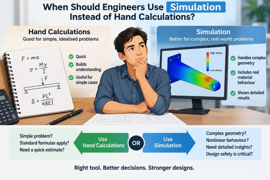
Hand calculations are not an outdated ritual. They are often the fastest way to understand a system, identify governing variables, and catch a result that simply cannot be right. But real equipment and structures can involve geometry, nonlinear behaviour, transient effects, and interacting physics that a compact equation cannot represent faithfully.
Simulation can reveal patterns that are difficult or impossible to calculate directly. It can also create a false sense of certainty when inputs, assumptions, or numerical settings are weak. A colourful contour plot is not automatically an engineering answer.
The useful choice is rarely hand calculations or simulation. It is deciding which tool is appropriate for the decision at hand, then using the other tool to check it.
🧭 Start With the Engineering Decision
Choose the method by asking what decision the analysis must support. Is the purpose to size a member, compare two design concepts, diagnose a failure, establish a safety margin, or predict performance over an operating cycle?
A simple, high-consequence decision may require both a transparent hand check and a carefully verified simulation. Conversely, an early concept study may only need an order-of-magnitude estimate. Analysis effort should be proportional to the uncertainty, consequence, and complexity of the decision.
✏️ What Hand Calculations Actually Do Well
Hand calculations use idealized equations, simplified free-body diagrams, charts, and sometimes small spreadsheets. Their strength is not merely speed: they expose the physical relationships between inputs and outputs.
For a simply supported beam under a known load, equations for reaction forces, bending moment, deflection, and stress can answer the core question directly. An engineer can see how span, load, elastic modulus, and section properties influence the result.
Use hand calculations when the governing behaviour is known, the geometry is simple, and a conservative idealization is reasonable.
🖥️ What Simulation Adds
Simulation approximates a physical system with a numerical model. Finite element analysis divides a structure into small elements; computational fluid dynamics divides a fluid region into small control volumes; system simulations represent connected components and their dynamic interactions.
This makes simulation valuable when local geometry, coupled effects, or changing conditions matter. It can estimate stress concentrations around holes, airflow through a complicated duct, or temperature gradients across an assembly.
Its output is still an approximation. The software solves the equations and assumptions supplied by the user—not the real object by default.
⚖️ The First Test: Is the Physics Simple?
Start by identifying the dominant physical mechanism. A static axial load, one-dimensional heat conduction, or steady pressure drop in a straight pipe often has a clear analytical model. These problems are excellent candidates for hand calculations.
Simulation becomes more justified when mechanisms interact. Consider a turbine blade that experiences centrifugal loading, thermal expansion, aerodynamic pressure, and vibration. Treating each effect separately may miss how one changes the others.
The question is not whether a system is “complicated.” It is whether simplification removes behaviour that could change the design decision.
📐 Geometry Is Often the Turning Point
Simple geometry supports simple mathematics. Prismatic beams, flat walls, circular pipes, and symmetric vessels commonly allow useful closed-form solutions—equations that can be solved directly.
Irregular cut-outs, fillets, welded attachments, branching flow paths, contact surfaces, and curved shells make direct equations less representative. A finite element model may then estimate how loads distribute through the actual shape.
Even so, model only the geometric detail that influences the result. Tiny cosmetic features can increase meshing effort without meaningfully changing global stiffness, stress, flow, or temperature.
🧱 Use Hand Methods for First-Pass Structural Sizing
Early structural design usually benefits from beam theory, section-property calculations, buckling estimates, and basic load paths. These calculations help select a plausible depth, thickness, material, or support arrangement before detailed modelling begins.
For example, a preliminary frame calculation can reveal whether loads travel mainly through bending, axial action, or bracing. That insight shapes the model and prevents the common mistake of building a highly detailed finite element model of an implausible concept.
Hand checks also establish expected reaction forces and approximate deflections for later comparison.
🔩 Simulate Local Stress Concentrations
A nominal stress calculation may be sufficient away from discontinuities. Near a hole, notch, sharp change in thickness, weld toe, or bolted connection, local stress can be substantially different from the average stress.
Simulation is useful when that local condition controls fatigue life, yielding, contact pressure, or crack initiation. The model must still use realistic constraints and load introduction; an artificial fixed boundary close to the feature of interest can produce misleading peak stresses.
Where applicable, established stress-concentration references and simplified methods remain valuable cross-checks.
🌊 Flow Problems Need a Regime Check
Before launching computational fluid dynamics, calculate quantities such as flow rate, velocity, Reynolds number, pressure loss, and expected temperature change. The Reynolds number helps indicate whether viscous or inertial effects dominate and whether turbulence may matter.
A straight pipe with fully developed flow may be handled accurately with standard correlations. CFD becomes more useful for strong separation, recirculation, mixing, complex manifolds, rotating equipment, or flow around detailed shapes.
CFD should not replace a pressure-drop calculation. The calculation provides a scale against which the simulation result can be judged.
🔥 Temperature Gradients Can Defeat Lumped Models
A lumped thermal model assumes a body has one uniform temperature. This can be appropriate when internal conduction is fast compared with heat transfer at the surface, or when only an average temperature matters.
Use a spatial thermal simulation when gradients drive the decision: thermal stress in a constrained component, hot spots on electronics, uneven curing, or temperature limits at an internal interface. Transient simulation is particularly useful when heating and cooling history matters.
A quick energy balance should still account for where heat enters, leaves, and accumulates.
⏱️ Steady State Is Not Always Enough
Hand calculations often assume equilibrium: loads, temperatures, and flows are constant. Many systems are designed around changes instead—startup, braking, switching, gusts, valve movements, seismic loading, or periodic cycling.
A transient simulation can show peak response and timing. For example, a thermal model may show that a component remains safe at steady operation but exceeds a limit during rapid warm-up because different materials expand at different rates.
Only model time dependence when the transient could change the design requirement. Otherwise, it may add cost without improving the decision.
〰️ Nonlinearity Is a Strong Signal
Linear models assume response scales with load: double the load, and displacement and stress double. They also usually assume small deformation, unchanged contact conditions, and constant material properties.
Simulation is often warranted when those assumptions fail. Common examples include plastic deformation, rubber-like materials, large deflection, buckling after instability begins, frictional contact, gaps opening or closing, and temperature-dependent properties.
Nonlinear analysis demands more judgement, not less. Convergence of the solver means it found a numerical solution; it does not prove that the physical model is correct.
🧩 Coupled Physics Requires Careful Scope
Some designs involve fields that affect each other: temperature changes stress, deformation changes a fluid passage, electromagnetic losses create heat, and flow-induced forces excite vibration. These are called coupled or multiphysics problems.
A fully coupled model may be appropriate when feedback is strong. In other cases, a sequential approach is enough: calculate heat generation, solve a thermal field, then apply that field to a structural model.
Start with the weakest coupling that captures the required effect. More coupling increases data needs, setup time, and opportunities for error.
🎯 Define the Required Accuracy First
There is no universal rule that simulation is “more accurate.” Accuracy depends on whether the model captures the relevant physics, inputs, boundaries, and numerical resolution.
| Decision need | Usually appropriate approach |
|---|---|
| Order-of-magnitude feasibility | Hand calculation or simple spreadsheet |
| Preliminary sizing and load path | Hand calculation, then a focused model if needed |
| Detailed local behaviour | Verified simulation plus simplified checks |
| Safety-critical final decision | Multiple independent checks, validation, and review |
If a concept only needs to distinguish whether a wall should be millimetres or centimetres thick, a detailed model may offer false precision. If a small temperature margin controls material selection, better resolution and validation may be necessary.
📥 Input Uncertainty Limits Output Value
Simulation can calculate many decimal places, but those digits do not reduce uncertainty in loads, friction, material properties, manufacturing variation, or operating conditions. The model may be precise numerically while uncertain physically.
For example, a contact analysis may be sensitive to bolt preload and friction coefficient. If neither is well known in service, reporting a single peak contact pressure as a definitive value is misleading.
Use ranges, sensitivity studies, and conservative assumptions where appropriate. Identify which uncertain input changes the conclusion most.
🧷 Boundary Conditions Are Part of the Model
Boundary conditions specify how a model is supported, loaded, heated, cooled, or connected to its surroundings. They are frequently the largest source of modelling error because real supports are rarely perfectly fixed, perfectly pinned, or uniformly loaded.
Think of a bracket attached by bolts. A fully fixed face may be acceptable for a preliminary estimate, but it may overstate stiffness and distort stresses near the attachment. Modelling bolts, contact, or connector stiffness may be justified if connection behaviour matters.
A detailed mesh cannot repair unrealistic boundary conditions.
🕸️ A Fine Mesh Is Not a Guarantee
In discretized simulation, a mesh breaks geometry into smaller pieces. Refining the mesh can improve representation of gradients, but it also increases computational cost and may expose singularities—mathematical stress spikes at idealized sharp corners or point loads.
Perform a mesh-convergence check for quantities that matter, such as force, displacement, pressure drop, or averaged stress over a meaningful region. If the result changes significantly as the mesh is refined, it has not yet stabilized.
Do not chase the highest single stress at a perfectly sharp, idealized corner without interpreting whether that peak represents a real failure mechanism.
✅ Verification Asks Whether You Solved the Model Right
Verification examines the numerical implementation. Are units consistent? Are loads balanced by reactions? Is the mesh adequate? Does a simpler version of the model match an analytical solution?
Useful verification habits include checking deformed shapes, plotting reaction forces, examining energy balance where relevant, and testing limiting cases. If a load is removed, the response should usually reduce accordingly; if symmetry is introduced, the model should reflect it.
Verification is an internal quality check before treating any output as an engineering prediction.
🔬 Validation Asks Whether the Model Represents Reality
Validation compares model predictions with physical evidence, such as test data, field measurements, established benchmark cases, or well-characterized equipment performance. It addresses a different question from verification.
A model can be perfectly set up and still be invalid for a particular application because it omits a relevant mechanism. For instance, a thermal model may solve conduction correctly while underestimating heat loss through an unmodelled mounting path.
When testing is limited, state clearly what has been checked and what remains uncertain.
🔄 Hand Calculations Are Simulation’s Best Companion
The strongest workflow often uses calculations before, during, and after simulation. Before modelling, estimates establish scales for loads, stresses, temperatures, and time constants. During modelling, they guide assumptions. After modelling, they test whether the answer is plausible.
If a finite element model predicts a deflection ten times larger than a beam estimate, do not immediately assume the simulation found hidden physics. First inspect material units, section orientation, supports, connections, and load application.
Agreement is not automatic proof, but major disagreement is a useful investigation signal.
🛠️ Build Models in Stages
A staged model is easier to trust than a complex model built all at once. Start with geometry and physics simple enough to compare with a hand calculation, then add detail only when it changes the question being answered.
- Create a baseline model with known loads and simple supports.
- Check reactions, displacement, and global trends.
- Add contacts, local geometry, nonlinear material behaviour, or thermal fields one at a time.
- Record how each addition changes the result and why.
This process makes assumptions visible and helps isolate the source of unexpected behaviour.
💡 Use Simulation to Compare Designs, Not Just Predict One Number
Simulation is especially effective for comparing alternatives under the same consistent assumptions. A designer can examine how rib placement changes stiffness, how manifold geometry affects flow balance, or how insulation location changes temperature gradients.
Relative comparisons can be more reliable than absolute predictions when some inputs remain uncertain, provided the uncertainty affects each option similarly. That condition should be examined, not assumed.
Use the results to explain trade-offs: reduced mass may increase vibration, while a lower pressure drop may worsen flow uniformity.
🧪 Reserve Experiments for Unknown Mechanisms
Neither hand methods nor simulation eliminates the need for testing when the governing behaviour is uncertain. Material behaviour after manufacturing, complex turbulence, wear, sealing performance, or human operation can be difficult to model with confidence.
Testing need not always mean a full prototype. A coupon test, instrumented subassembly, flow visualization exercise, or controlled thermal trial may provide the missing input or validate the critical part of a model.
Use simulation to decide what to test and where to measure. Use tests to improve the model.
💰 Consider Time, Cost, and Reuse
A detailed simulation has setup, review, and interpretation costs. It is worthwhile when it avoids expensive iterations, supports a high-risk decision, or creates a reusable model for a family of products.
For a one-off, low-risk part with conventional loading, a documented calculation may be faster, clearer, and more economical. For a product expected to evolve through many variants, a parameterized model can pay back the initial effort.
The right tool is the one that produces dependable information soon enough to influence the design.
📋 Documentation Makes Analysis Reviewable
An analysis result should allow another engineer to understand what was done and what it means. Record the design question, geometry revision, materials, loads, boundary conditions, assumptions, solver type, mesh approach, checks performed, and applicable limitations.
For hand work, show diagrams, units, equations, and sources of input values. For simulation, include clear images of constraints and loads—not only attractive result contours.
Good documentation turns a model from a private calculation into a reviewable engineering artifact.
🚩 Common Reasons Simulation Misleads
Most poor results do not come from a mysterious software failure. They arise when the model answers a different question from the one the engineer intended to ask.
- Applying loads to unrealistically small areas or points.
- Using default material data without checking the relevant temperature, direction, or strain-rate range.
- Fixing every degree of freedom at a support that is actually flexible.
- Ignoring contacts, preload, or clearance when they control stiffness.
- Reporting a local numerical peak as a physical stress limit.
- Accepting a result without an independent scale check.
These errors are preventable through clear problem definition and disciplined review.
🧠 Avoid the “Software Will Decide” Mindset
Simulation packages are powerful because they automate equation solving, meshing, and visualization. They do not automate engineering judgement. A solver cannot determine whether the chosen load case is credible or whether a simplified connection reflects assembly reality.
Engineers should be able to explain the expected direction of change before running a model. Will a thicker web reduce bending stress? Will a restricted passage increase pressure loss? If the result contradicts basic physical reasoning, investigate.
Software proficiency matters, but physical intuition remains the first line of quality control.
👥 Independent Review Scales With Consequence
Complex or high-consequence analysis benefits from a second set of eyes. A reviewer can challenge assumptions, inspect boundary conditions, reproduce key calculations, and ask whether the result addresses the stated requirement.
Review is most effective when it begins before a model is complete. Discussing load paths, acceptance criteria, and likely failure modes early can prevent a polished but irrelevant analysis later.
For work governed by project, company, or regulatory requirements, follow the applicable review and documentation procedures rather than relying on a general workflow alone.
🧮 A Practical Selection Checklist
Before deciding, work through these questions in order:
- What decision must this analysis support, and what margin or accuracy is needed?
- What physical mechanism is likely to govern?
- Can a simple equation represent the geometry and boundary conditions conservatively?
- Would local geometry, time dependence, nonlinearity, or coupled physics change the conclusion?
- Are the input data good enough to justify a detailed model?
- How will the result be verified, validated, documented, and reviewed?
If the answers show simple physics and robust assumptions, begin with calculations. If they reveal interactions that materially affect performance or safety, add simulation with a defined verification plan.
🏁 The Core Principle: Use the Simplest Defensible Model
Hand calculations and simulation are not competing badges of sophistication. They are tools with different strengths. Calculations create understanding, transparency, and rapid checks; simulations represent detail, interactions, and spatial variation.
The best analysis is not the one with the most elements, the longest report, or the neatest contour plot. It is the one whose assumptions fit the decision, whose limitations are understood, and whose conclusions remain credible when checked from another direction.
Start simple, add complexity only when it changes the engineering answer, and never let numerical detail outrun the quality of the inputs.
Engineers should use simulation when simplified calculations cannot represent the behaviour that controls the decision—and should use hand calculations throughout to keep the simulation honest. 📐🖥️🔍