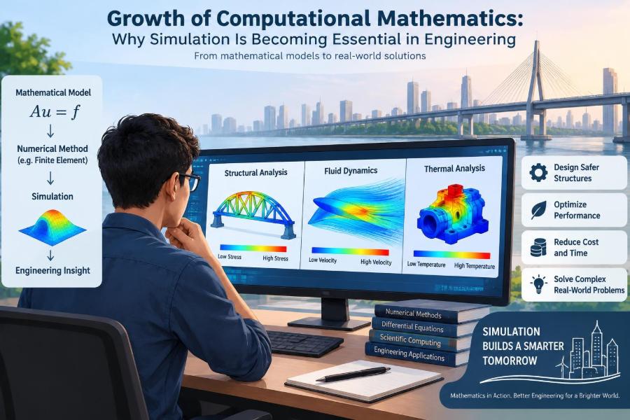

A bridge design may look complete on a screen long before a single beam is fabricated. Engineers can apply traffic loads, gusting wind, temperature changes, and even earthquake-like motion to its digital model, then watch where stresses gather and how the structure deflects.
The same pattern appears in quieter places: an engineer tests whether a phone battery will overheat, a manufacturer explores a new turbine blade, and a water utility examines what happens when a pump fails. Building and breaking a physical version of every option would be slow, expensive, and sometimes unsafe.
This is why computational mathematics has moved from a specialist activity to a central engineering capability. It turns mathematical descriptions of physical systems into calculations that can be explored, compared, and improved.
Simulation does not replace engineering judgment or experimental testing. But when it is built and checked carefully, it gives engineers a practical way to reason about systems before the real-world consequences arrive.
🧭 What Computational Mathematics Means
Computational mathematics is the use of mathematical models, numerical methods, and computing to solve problems that cannot be handled conveniently by hand. The aim is not simply to produce numbers; it is to represent a physical, biological, financial, or engineered process well enough to make useful decisions.
A simulation is the executable version of that model. It takes inputs such as geometry, material properties, boundary conditions, and operating conditions, then estimates how the system behaves over space or time.
🔢 Why Exact Equations Are Often Not Enough
Engineering is built on equations, but many realistic equations have no simple closed-form answer. Fluid flow around a car, heat moving through a layered battery pack, and vibration in a complex machine involve many interacting variables and irregular shapes.
Even when an exact solution exists for an idealized case, the real design may include holes, joints, changing materials, nonlinear behavior, or time-varying loads. Computational methods make these complications manageable rather than ignoring them.
🧩 From Physical System to Mathematical Model
Every simulation begins with choices. An engineer identifies the quantities that matter, such as displacement, pressure, temperature, voltage, or concentration, and writes relationships based on conservation laws and material behavior.
For example, a thermal model may balance heat entering, leaving, and being stored in each part of a device. The model is always a simplification. Its value depends on whether the simplifications preserve the behavior relevant to the decision.
🗺️ The Role of Assumptions
Assumptions are not flaws to hide; they are the boundaries of a model. A structural analysis might assume small deflections, a fluid model might treat flow as incompressible, or a traffic model might represent drivers as average agents.
The risk comes when assumptions are invisible or inappropriate. If a rubber component deforms heavily, a small-deformation model can give a neat result that is physically misleading. Good simulation practice records assumptions and tests their effect.
🧱 Discretization: Dividing the Problem into Pieces
Computers generally cannot calculate a continuous field at infinitely many points. Discretization replaces the continuous domain with a finite set of pieces: elements, cells, nodes, or time steps.
Think of approximating a curved coastline with connected short line segments. More segments can capture more detail, but they also increase the calculation. Choosing an adequate level of detail is one of the most consequential modeling decisions.
🔺 Finite Element Analysis for Structures
Finite element analysis, often called FEA, divides a component or structure into small elements connected at nodes. The solver estimates how those pieces move and transmit force, producing fields of displacement, strain, and stress.
FEA is used for brackets, buildings, medical implants, chassis components, and many other structures. It is particularly useful near holes, fillets, welds, and connections, where simple hand calculations may not reveal concentrated stresses.
🌊 Computational Fluid Dynamics for Flow
Computational fluid dynamics (CFD) calculates the motion of liquids and gases. Engineers use it to investigate pressure loss in pipes, airflow through rooms, cooling channels in electronics, mixing in process equipment, and aerodynamic drag.
Fluid behavior can change sharply with turbulence, separation, and rotating machinery. CFD can expose patterns that are difficult to see experimentally, but its answers are sensitive to turbulence models, mesh quality, and inlet conditions.
🌡️ Heat Transfer Models in Everyday Designs
Heat simulation affects products that rarely look mathematical: insulated buildings, electric motors, ovens, LED assemblies, data centers, and battery enclosures. It estimates where temperatures rise, how quickly they change, and whether cooling paths are sufficient.
Temperature also changes materials and dimensions. A model that treats thermal and mechanical behavior separately may miss thermal expansion, stress, or loss of strength at high temperature.
⚡ Multiphysics Captures Coupled Behavior
Many important systems involve more than one physical process. An electric motor couples electromagnetic fields, heating, structural forces, and rotation. A lithium-ion battery couples electrical behavior, heat generation, and electrochemical processes.
Multiphysics simulation links these models so that one result becomes another model’s input. This adds realism, but it also adds uncertainty and computational cost. Coupling is most valuable when the interactions can materially change a design decision.
⏱️ Time Changes the Question
A static analysis asks what happens under a fixed load. A transient analysis asks how behavior evolves: a pressure pulse moves down a pipe, a vehicle hits a bump, or a room warms through the afternoon.
Time stepping introduces another trade-off. Steps that are too large can miss rapid events or create unstable calculations; extremely small steps can make an otherwise sensible model impractical to run.
🖥️ Computing Power Has Changed the Workflow
Faster processors, larger memory, cloud resources, and graphics processing units have expanded the scale of problems engineers can investigate. More importantly, they allow teams to compare alternatives earlier, rather than reserving simulation for a final check.
More computing power does not automatically create better models. It can make a bad setup produce an answer faster. Mathematical understanding remains necessary to decide what should be calculated in the first place.
🔄 Simulation Supports Iteration, Not One Final Answer
Design is usually a cycle: define a concept, simulate it, inspect the result, revise the design, and repeat. Early models may be rough but useful for eliminating weak ideas before detailed work begins.
Later models can add refined geometry and operating conditions. This staged approach prevents teams from spending days on high-fidelity analysis of a concept that basic engineering reasoning would already reject.
🎯 Virtual Prototypes Reduce Physical Trial Burden
Physical prototypes remain essential, especially where failure has serious consequences. Yet virtual prototypes can narrow the options before tooling, materials, laboratory time, or field access are committed.
Consider a hypothetical pump housing with several candidate wall thicknesses. Simulation can compare stiffness and flow resistance across the options, helping engineers choose which versions deserve physical testing. It reduces trial burden; it does not certify the final product alone.
📏 Design Optimization Searches Systematically
Optimization connects a simulation to a stated objective, such as minimizing mass, reducing pressure drop, increasing fatigue life, or keeping temperature below a limit. The algorithm varies selected design parameters and evaluates the consequences.
The crucial question is not merely “what is optimal?” but “optimal under which objectives and constraints?” A lighter component may cost more to manufacture or become harder to inspect. Useful optimization reflects the full engineering problem.
🧠 Digital Twins Extend Models into Operation
A digital twin is a model connected, to varying degrees, with information from a real asset. Sensor data may update estimates of performance, identify deviations, or support maintenance planning.
Not every digital representation is a full twin. A static CAD model is not one, and a dashboard alone is not one. The practical value comes from a credible link between physical measurements, model predictions, and an operational decision.
🏗️ Structural Engineering: Seeing Load Paths
In structures, simulation helps engineers understand load paths: the routes forces take through beams, slabs, joints, and foundations. It can show whether an opening redirects stress into an unexpected region or whether a connection is much stiffer than assumed.
However, a detailed color contour is not proof of safety. Supports, connections, construction sequence, and material variability must reflect the real structure. Local stress peaks also require interpretation rather than automatic acceptance.
🚗 Mechanical and Manufacturing Applications
Mechanical engineers simulate vibration, contact, wear, forming, machining, and fatigue. Manufacturing simulations can estimate how molten material fills a mold or how residual stresses develop during welding or additive manufacturing.
These tools matter because production changes the part. A component may meet strength requirements in a clean CAD geometry but behave differently after forming, heat treatment, surface finishing, or assembly preload.
🏙️ Civil, Environmental, and Infrastructure Systems
Computational models also operate at city and landscape scales. They can represent drainage networks, contaminant transport, traffic flow, foundation response, and energy use in buildings.
Inputs at this scale are often uncertain: rainfall patterns, soil layers, occupancy, maintenance condition, and future demand vary. Scenario analysis is therefore often more honest than presenting one forecast as a guaranteed outcome.
🩺 Biomedical Engineering Requires Extra Care
Models of blood flow, implants, medical devices, and tissue mechanics can support design and research. Their appeal is clear: direct measurements may be difficult, invasive, or unavailable for each individual case.
But biological systems vary greatly, and simplified material or boundary assumptions can matter enormously. Simulation in this area requires careful validation and must not be treated as a substitute for appropriate clinical, regulatory, or safety evaluation.
✅ Verification Asks: Did We Solve the Equations Right?
Verification concerns the numerical implementation. It asks whether the code, mesh, solver settings, and calculation process solve the chosen mathematical model correctly.
Common checks include refining the mesh, reducing time-step size, comparing with a known benchmark, and checking conservation of mass or energy. If results shift substantially as the mesh is refined, the original resolution may not be adequate.
🔍 Validation Asks: Are These the Right Equations?
Validation compares model predictions with measurements from the real system or a relevant experiment. A verified calculation can still be wrong for reality if its material law, load conditions, or boundary conditions are unrealistic.
Verification and validation are often confused. The first establishes confidence in solving the model; the second tests whether the model represents the intended physical situation well enough for its purpose.
📊 Uncertainty Should Be Modeled, Not Hidden
Material properties, loads, dimensions, sensor readings, and operating conditions all have uncertainty. Rather than reporting only one output, engineers can test ranges, run scenarios, or use probabilistic methods when adequate input information exists.
A result such as “this design is robust across plausible load variation” is often more useful than a highly precise-looking value based on one uncertain assumption. Precision in display should not be mistaken for certainty in knowledge.
🚨 The Danger of Attractive Color Plots
Simulation software can produce persuasive contours, animations, and dashboards. Visual clarity is valuable, but it can create false confidence when viewers do not know the scale, assumptions, or numerical limitations behind the image.
- Check units and color-bar limits before comparing plots.
- Ask where loads enter and where constraints are applied.
- Inspect reaction forces and conservation checks.
- Look for mesh dependence and physically implausible patterns.
A striking plot is evidence to investigate, not a conclusion by itself.
🧷 Boundary Conditions Often Control the Result
Boundary conditions describe how a model interacts with its surroundings: fixed supports, applied forces, inlet flow rates, ambient temperatures, electrical contacts, or frictional interfaces. They are frequently harder to define than the governing equations.
For instance, modeling a bolted component as perfectly fixed may make it appear much stiffer than its actual joint. When results are surprising, boundary conditions deserve early scrutiny.
🕸️ Mesh Quality Is an Engineering Decision
Fine meshes are useful near sharp gradients, contacts, thin layers, and geometric details. A uniformly tiny mesh everywhere, however, may consume resources without improving the answer that matters.
Engineers commonly use a coarser mesh in calm regions and refinement where physics demands it. Quality also matters: distorted elements can degrade accuracy even when their number is large.
🧪 Experiments and Simulation Work Best Together
Experiments provide real behavior; simulations provide coverage across conditions that may be difficult to test individually. Together they form a stronger workflow than either method alone.
Testing can calibrate uncertain parameters and reveal missing mechanisms. Simulation can then help interpret measurements, design the next experiment, and extend insights to configurations that were not physically tested.
👥 Collaboration Is Part of Model Quality
A credible model often requires input from designers, analysts, manufacturing specialists, operators, and test engineers. The analyst may understand numerical settings, while an operator knows that a machine routinely experiences a startup condition absent from the written requirement.
Clear communication includes stating model scope, assumptions, input sources, checks performed, and decisions supported. This makes results reviewable and prevents a simulation file from becoming an unexplained black box.
📚 Skills That Make Simulation Useful
Software familiarity matters, but it is not sufficient. Effective practitioners need mathematical foundations, physical intuition, data handling skills, and the discipline to question outputs.
- Calculus and differential equations for governing behavior
- Linear algebra for large systems of numerical equations
- Probability and statistics for uncertainty and measurement data
- Programming or scripting for repeatable workflows and analysis
- Communication for explaining limitations alongside results
🛠️ A Sensible Workflow for New Analysts
Start with the decision, not the software. Ask what must be learned, which output would change the design, and what level of confidence is required.
- Sketch the physical system and identify dominant effects.
- Make a simple hand estimate or reduced model.
- Build the simplest simulation that can address the question.
- Check units, constraints, balances, and convergence.
- Refine only where results and decisions justify it.
- Compare with measurements or trusted references when possible.
This process makes sophisticated tools more reliable because it anchors them to engineering reasoning.
⚖️ When Simulation Is Not the Best First Tool
A quick calculation, physical test, established design rule, or direct measurement may be faster and more dependable for a straightforward problem. Simulation is not automatically the responsible choice merely because it is available.
It is less suitable when crucial input data are unknown, when the relevant physics cannot be represented credibly within the available time, or when a simple test can answer the decision more directly. Tool choice should follow the risk and question.
🌱 Why Computational Mathematics Will Keep Growing
Engineering systems are becoming more connected, customized, and constrained by energy, materials, safety, and environmental performance. Those pressures create more design interactions than isolated formulas can conveniently capture.
At the same time, automation, sensors, and machine-learning methods are changing parts of the workflow. These methods can accelerate surrogate modeling, pattern detection, or design exploration, but they still require sound data, physical constraints, and independent checking.
🏁 The Core Principle: Simulation Is Disciplined Approximation
Simulation becomes essential not because it predicts everything perfectly, but because it lets engineers test reasoned approximations before committing to costly or risky actions. Its strength comes from combining mathematics, computing, experiments, and professional judgment.
The best result is rarely the most colorful image or the largest model. It is the answer that is sufficiently credible, transparent, and timely to improve a real engineering decision.
Computational mathematics earns its place in engineering when models are treated as evidence to test and refine—not as unquestionable substitutes for reality. Used that way, simulation helps turn complex systems into decisions people can examine, explain, and improve. 📐💻🔧