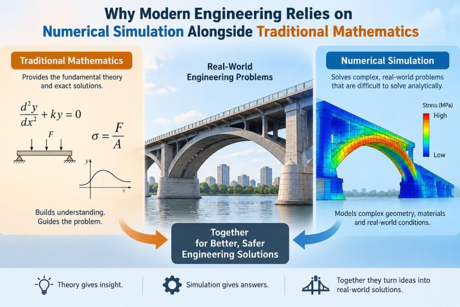

A bridge engineer may begin with equations for bending, shear, vibration, and material strength. Those equations are not decorative academic exercises: they establish what loads matter, which dimensions are critical, and what failure modes deserve attention.
But a real bridge has joints, changing cross-sections, wind gusts, temperature gradients, moving vehicles, construction tolerances, and materials that do not behave perfectly uniformly. Solving every one of those details exactly by hand is usually impossible.
The same pattern appears when designing a quieter electric motor, predicting airflow around a drone, estimating heat loss from a battery pack, or checking whether a medical device can survive repeated loading. Traditional mathematics provides the language and structure. Numerical simulation makes difficult versions of the problem computationally tractable.
Modern engineering depends on both because neither is sufficient alone. A simulation without mathematical understanding can produce convincing nonsense, while an elegant closed-form equation can omit the very details that control a real design.
🧭 Mathematics Is Still the Starting Point
Engineering simulation is not an alternative to mathematics. It begins by translating a physical situation into mathematical relationships: conservation of mass, momentum, energy, electric charge, or other relevant quantities.
For example, fluid-flow software does not “know” how air moves by intuition. It approximates the governing equations of fluid mechanics. Structural software similarly works from equations that connect loads, deformation, stress, and material response.
Mathematics determines what the model means; computation determines how far the model can be carried.
📏 What Traditional Analytical Mathematics Does Well
An analytical solution is an explicit mathematical result obtained from equations under stated assumptions. The familiar beam-deflection formulas taught in mechanics courses are examples: with a defined load, geometry, and material model, they give direct expressions for displacement and stress.
These solutions are fast, transparent, and valuable for checking scale. They reveal how an output changes when a parameter changes, often more clearly than a large software model can.
- A pipe-flow relation can estimate pressure drop before detailed layout work begins.
- A circuit equation can identify the expected time constant of a charging system.
- A vibration formula can flag whether an operating speed may approach resonance.
Such calculations remain essential in concept design, education, reviews, and independent verification.
🧩 Why Real Engineering Problems Become Hard
Closed-form solutions usually require idealization. A beam may be assumed straight, slender, homogeneous, and linearly elastic; a fluid may be treated as steady and incompressible; a thermal problem may assume constant conductivity.
Those assumptions are often sensible, but real products combine complications. Geometry may include holes, fillets, welds, contact surfaces, sharp changes in thickness, and multiple materials. Loads can move, vary with time, or depend on the response of the structure itself.
The difficulty is not that the governing laws disappear. It is that their combined equations no longer have a practical exact solution.
🔢 The Central Idea of Numerical Approximation
Numerical methods replace one difficult continuous problem with many smaller, manageable calculations. Rather than solving for temperature at every possible point in a metal housing, the model calculates it at a finite set of locations and estimates the behavior between them.
The answer is therefore approximate, but the approximation can be made useful by choosing an appropriate method, sufficiently fine resolution, stable algorithms, and realistic inputs.
This is similar to representing a curved coastline with many short straight segments. More segments can capture more detail, but only if the underlying map and measurements are trustworthy.
🕸️ Discretization Turns Physics into Computation
Discretization is the process of dividing a continuous domain into discrete pieces. In structural finite element analysis, a component is divided into small elements connected at nodes. In computational fluid dynamics, a flow region is divided into cells.
Within each piece, the software uses simplified mathematical representations. It then assembles many local equations into a much larger system that represents the full object or region.
The physical object has not become a collection of boxes or triangles. The mesh is a computational representation, and its suitability must be assessed.
🧱 Finite Element Analysis for Structures
Finite element analysis, commonly called FEA, is widely used to estimate deformation, stress, vibration, buckling, and heat transfer in solids. It is particularly useful when geometry is irregular or when loads are distributed in complicated ways.
Consider a bracket with mounting holes and a curved transition into a supporting arm. A hand calculation can estimate the overall bending load. FEA can then investigate how load flows around the holes and whether local regions need smoother geometry or more material.
However, a colorful stress plot is not automatically a design decision. Local peaks may represent a meaningful stress concentration, a modeling artifact, or a mathematical singularity near an idealized sharp constraint.
🌬️ Computational Fluid Dynamics for Flow
Computational fluid dynamics, or CFD, approximates fluid motion, pressure, temperature, and related transport processes. Engineers use it for ducts, pumps, vehicle aerodynamics, heat exchangers, ventilation, and many other systems.
A simple pressure-drop equation may be adequate for a straight pipe. CFD becomes useful when flow separates around obstacles, turns through complex passages, mixes with another stream, or transfers heat across intricate surfaces.
Flow simulations are sensitive to boundary conditions and turbulence modeling. Predictions near walls, wakes, and rotating equipment can require particular care because the physical flow contains scales of motion that a practical simulation cannot always resolve directly.
🔥 Thermal Simulation Connects Many Disciplines
Heat rarely stays in one engineering category. A battery generates heat electrically, conducts it through solid parts, may transfer it to air or coolant, and changes performance as its temperature changes.
Thermal simulation lets engineers estimate temperature fields rather than relying only on one average value. That distinction matters when a small hot spot limits component life or triggers a protection system.
Material properties, contact resistance, airflow, radiation, and ambient conditions all affect the result. A thermal model with a perfectly bonded interface may look reassuring while missing the resistance introduced by an actual assembly gap.
⚡ Circuit and Electromagnetic Models Extend the Same Logic
Electrical engineers also use numerical models when circuit behavior, electric fields, magnetic fields, and geometry interact. Lumped circuit models work well when components can be represented by idealized resistors, capacitors, inductors, and sources.
At higher frequencies or within compact power electronics, physical layout can matter strongly. Parasitic inductance, electric-field concentration, magnetic saturation, and electromagnetic interference may need more detailed analysis.
The principle is unchanged: start with the simplest model that addresses the decision, then introduce detail only where it changes the conclusion.
🧪 Materials Rarely Behave Like Perfect Textbook Solids
Introductory calculations often treat materials as linear elastic: double the load and deformation doubles, then the material returns to its original shape when unloaded. This is useful within a limited range.
Real engineering may involve plastic deformation, creep, fatigue, anisotropy, damage, temperature dependence, or rate-dependent behavior. Rubber, composites, foams, biological materials, and welded assemblies can be especially difficult to idealize.
A material model should match the question. Using a complex constitutive model without reliable test data can add apparent sophistication without adding accuracy.
🧷 Boundary Conditions Can Dominate the Result
A simulation must specify how the model interacts with the outside world. These boundary conditions include supports, applied loads, pressures, temperatures, flow rates, voltages, contacts, and constraints.
They are frequently more uncertain than the governing equations. A part described as “fixed” may actually be bolted through a flexible frame. A prescribed airflow may vary substantially with fan operating point, duct losses, and obstruction.
Before refining a mesh, ask a more basic question: does the model represent how the object is actually held, loaded, cooled, powered, or connected?
🔗 Contact Makes Mechanical Models More Realistic—and More Difficult
When two components touch, they may separate, slide, stick, transfer load unevenly, or develop friction. Contact changes the load path as deformation occurs, making the problem nonlinear.
A bolted joint is a useful example. Its behavior depends on preload, friction, stiffness of the connected parts, hole clearance, and loading direction. Replacing it with a permanently bonded connection may be acceptable for one early estimate and misleading for another.
Contact modeling often increases computational cost and convergence difficulty. It should be introduced deliberately, with a clear understanding of what design behavior it needs to capture.
📈 Linear and Nonlinear Problems Need Different Expectations
A linear model assumes proportional response and usually unchanged geometry and contact state. It is fast and often appropriate for small deformations in ordinary operating conditions.
Nonlinear analysis accounts for effects such as yielding, large shape changes, changing contact, or nonlinear material behavior. It can reveal important behavior that a linear model misses, but it requires more inputs, more careful solution settings, and closer scrutiny.
Nonlinear does not automatically mean better. If the available load history or material data are poorly known, a detailed nonlinear output may still carry substantial uncertainty.
⏱️ Static Results Cannot Answer Every Time-Dependent Question
A static simulation estimates response to loads applied slowly enough that inertia is negligible. It is useful for many strength and stiffness questions, but it does not represent impact, vibration, wave propagation, startup transients, or cyclic loading.
Dynamic simulation introduces time, mass, damping, and changing loads. A machine frame may be structurally strong under a static force yet vibrate excessively when an unbalanced rotor passes through a natural frequency.
Choosing between static, modal, harmonic, transient, or explicit dynamic analysis is a physics decision, not merely a software-menu choice.
🎵 Natural Frequencies Explain Why Stiffness Alone Is Not Enough
Every structure has natural modes of vibration: characteristic patterns in which it tends to move. A modal analysis estimates their shapes and frequencies.
If excitation from a motor, road surface, rotating blade, or repeated process aligns with a natural frequency, resonance can amplify motion. Damping limits that amplification, but it does not remove the need to consider it.
Analytical vibration estimates are excellent early warnings. Simulation becomes especially useful when mass distribution, supports, and geometry make the real mode shapes less obvious.
🎯 Mesh Quality Is a Modeling Decision
A mesh that is too coarse may smooth away steep stress, temperature, or velocity gradients. A mesh that is extremely fine everywhere may consume time and memory without improving the decision.
Good practice is to refine where physics changes rapidly: around holes, contact regions, thin boundary layers, sharp thermal paths, or areas where a result will be assessed. Smooth regions often need fewer elements or cells.
Element shape also matters. Distorted elements can reduce accuracy or cause solution problems, even when the total element count appears impressive.
🔍 Mesh Convergence Tests Whether Detail Changes the Answer
A mesh convergence study compares key outputs as the mesh is refined. The goal is not to obtain the largest possible model; it is to show that the result relevant to the engineering decision has stabilized sufficiently.
For a bracket, useful outputs may include displacement at a mounting point, reaction force, or stress averaged away from a singular corner. For CFD, they may include pressure drop, lift, heat-transfer rate, or flow split.
If a key result shifts significantly every time the mesh changes, the model is not yet robust enough to support a confident conclusion.
🚩 Singularities Are Not Physical Infinite Stresses
Some idealizations generate stress values that rise indefinitely as the mesh is refined. Common causes include perfectly sharp re-entrant corners, point loads, and fully fixed edges that do not represent the real load distribution.
The displayed maximum can then be mathematically real within the idealized model but physically unhelpful. Engineers should inspect the stress pattern, improve the representation of the load or geometry, and assess stress over a meaningful region.
Never accept or reject a design solely because of an unexamined peak value. The question is whether the model captures a credible failure mechanism.
✅ Verification Asks Whether the Equations Were Solved Correctly
Verification concerns the numerical implementation. Did the chosen elements, mesh, solver settings, and model setup solve the stated mathematical problem accurately enough?
Useful verification activities include checking units, examining force or energy balance, reviewing mesh convergence, comparing with an analytical limiting case, and confirming that constraints do not create unintended rigid-body motion.
Software may perform its algorithms correctly while the user supplies an unsuitable model. That is why verification alone is not enough.
🧭 Validation Asks Whether the Right Physical Problem Was Modeled
Validation compares model predictions with relevant physical evidence, such as measured temperatures, displacement tests, pressure measurements, or observed operating behavior. It addresses whether the model represents reality adequately for its intended use.
A model can be verified but not validated: it may precisely solve the wrong boundary conditions. Conversely, agreement with one measurement does not prove that every predicted feature is accurate.
Validation is strongest when it covers the quantities and operating range that matter to the decision. It also requires attention to measurement uncertainty and differences between the test setup and the modeled setup.
📊 A Simple Comparison of the Main Approaches
| Approach | Best use | Main strength | Main limitation |
|---|---|---|---|
| Hand calculation | Early sizing and checks | Fast, transparent, explanatory | Requires simplifying assumptions |
| Analytical model | Idealized systems and parameter insight | Shows relationships clearly | Often cannot include full geometry |
| Numerical simulation | Complex geometry and coupled physics | Represents detailed spatial behavior | Depends strongly on inputs and setup |
| Physical test | Validation and final performance evidence | Captures real behavior | Can be costly, slow, or difficult to instrument |
These methods are complementary rather than competing. The most reliable programs move between them instead of asking one method to do every job.
🪜 The Best Workflow Moves from Simple to Detailed
A defensible simulation usually begins before software is opened. Define the design question, identify the governing physics, and estimate the expected scale of the answer with a simple calculation.
- State the decision the analysis must support.
- Define geometry, material behavior, loads, supports, and operating conditions.
- Build the simplest credible model.
- Check units, reactions, trends, and limiting cases.
- Refine detail only where it affects the decision.
- Compare predictions with suitable test or operational data when possible.
This progression prevents the common mistake of building a detailed model before understanding the problem.
🧠 Engineering Judgment Chooses the Right Fidelity
Model fidelity is the degree of detail included in a model. High fidelity is not synonymous with high value. A full assembly model with every fastener and surface texture may be unnecessary if the decision concerns overall stiffness during an early concept comparison.
On the other hand, a simplified model may be inadequate when a local seal, thermal hotspot, weld toe, or vibration mode is safety-critical or expensive to change later.
Choose fidelity according to consequence, uncertainty, available data, and the stage of design. A model should be no more complex than needed to answer the question credibly.
🔄 Simulation Accelerates Design Iteration
When used well, simulation lets teams compare alternatives before committing to prototypes. Engineers can vary thickness, geometry, material, cooling paths, or operating conditions and observe which changes are likely to matter.
This is especially valuable when prototypes are slow to manufacture or difficult to test under extreme conditions. It can also reveal trade-offs: a stiffer part may be heavier, a cooler component may require more pumping power, and a lower-drag shape may be harder to manufacture.
Simulation narrows the design space; it does not eliminate the need to decide which trade-offs are acceptable.
🧮 Automation Makes Repeated Analysis Practical
Parameter studies and optimization use scripts or built-in tools to run many variations of a model. Rather than changing one dimension manually, an engineer can examine a structured range and identify sensitivities.
Optimization is most trustworthy when constraints, objectives, and assumptions are explicit. An algorithm can minimize mass, for example, but may propose shapes that are difficult to manufacture, inspect, or maintain unless those requirements are included.
Automation increases speed, not judgment. A fast process can repeat a flawed setup hundreds of times.
⚠️ Attractive Visuals Can Create False Confidence
Modern simulation tools produce smooth contours, animations, and three-dimensional renderings. Those visuals are useful for communication, but they can make uncertain results appear more certain than they are.
Good reporting should state assumptions, material data sources, load cases, boundary conditions, mesh evidence, solver limitations, and the quantity actually being judged. A plot without context is not an engineering argument.
When presenting results, distinguish clearly between computed predictions, measured observations, and assumptions used to connect them.
🛠️ Common Modeling Mistakes—and Better Habits
- Mistake: Applying a load to one node because it is convenient. Better habit: distribute it over the physical contact area or use an appropriate connection model.
- Mistake: Treating every joint as perfectly fixed. Better habit: represent stiffness, contact, or flexibility when it affects load paths.
- Mistake: Trusting default material properties. Better habit: confirm the grade, temperature range, directionality, and relevant condition.
- Mistake: Reporting only a maximum contour value. Better habit: inspect distributions, convergence, and physical plausibility.
- Mistake: Ignoring units. Better habit: perform independent dimensional and order-of-magnitude checks.
These habits are transferable across structural, thermal, fluid, and electrical analyses.
👥 Collaboration Improves Model Credibility
Useful models often require input from people beyond the analyst. A manufacturing engineer may identify an assembly gap that changes thermal contact. A test engineer may know that a fixture is flexible. An operator may describe a transient condition absent from the original load case.
Review is not simply a final approval step. Early conversations can prevent a technically polished model from answering the wrong practical question.
Clear communication also helps non-specialists use results appropriately. Decision-makers need the conclusion, assumptions, margin, limitations, and next action—not just solver terminology.
🎓 Skills Students and Professionals Should Build
Software familiarity is valuable, but durable capability rests on fundamentals. Learn to draw free-body diagrams, use conservation laws, estimate orders of magnitude, interpret differential equations, and state assumptions plainly.
Then practice numerical thinking: understand discretization, convergence, conditioning, stability, error sources, and sensitivity. Writing a small numerical method in a programming environment can be an excellent way to see what commercial tools automate.
Most importantly, develop the habit of asking, “What observation would make me doubt this result?” That question leads naturally to checks, tests, and better models.
🌍 Simulation Supports Responsible Engineering, Not Risk-Free Engineering
Simulation can reduce unnecessary prototypes, identify inefficient designs, and investigate conditions that are hazardous or impractical to reproduce early in development. It also helps engineers study systems before resources are committed.
Yet models can fail quietly when assumptions are hidden or data are weak. Safety-critical work requires suitable margins, review, testing, and compliance with the applicable professional and organizational processes.
Responsible use means being explicit about uncertainty. A model is evidence with a scope, not a guarantee.
🏁 The Core Principle: Combine Insight, Computation, and Evidence
Traditional mathematics provides governing laws, useful simplifications, and independent checks. Numerical simulation extends those laws to geometries, interactions, and operating conditions that resist hand solution.
Physical testing anchors predictions to reality. Engineering judgment connects all three by selecting assumptions, assessing uncertainty, and deciding whether the available evidence is adequate for the consequence of the decision.
The strongest engineering work does not choose between equations and simulation; it uses equations to understand, simulation to explore, and evidence to confirm.
Numerical simulation is most valuable when it remains accountable to physical laws, simple checks, and real-world evidence—not when it is treated as a black-box answer. That balanced approach turns computation into dependable engineering insight. 📐🧪⚙️